 Four-Faith IoT
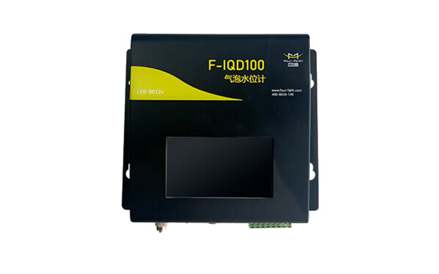
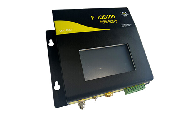
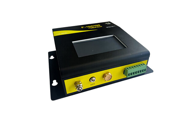
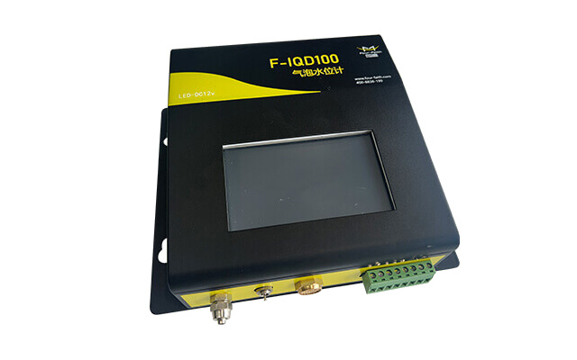
High-precision water level measurement via bubbler pressure induction .Full temperature range + dual linear automatic .compensation.Adjustable liquid density parameter for various water bodies.Freely configurable zero point & base elevation calibration.Customizable timed sampling interval.4.3-inch industrial touchscreen for real-time data & historical record onsite viewing.Local storage for up to 500,000 records; data retained after power failure.Over-range local alarm function.Hardware lightning & ESD protection.Embedded OS auto-restart upon system faults.
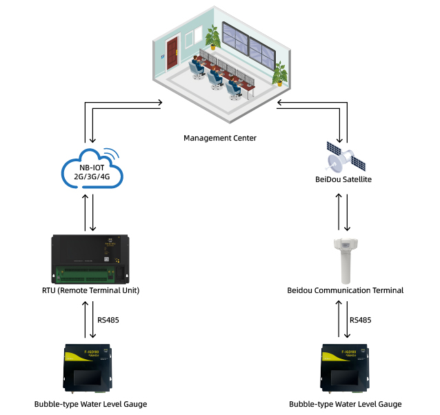
External 2G/3G/4G/NB-IoT/Beidou telemetry terminal for cloud remote data transmission . Extended air tubes (max length 300m) .Custom measuring ranges
F-IQD100 is a high-precision intelligent bubbler water level monitor. It adopts a micro piston pump pressure induction principle. No probe submersion or stilling well construction is required; water level is converted by transmitting hydrostatic pressure via air tubes. Equipped with touch screen interaction, local mass storage and multiple standard communication interfaces, it adopts full-range temperature & linear compensation algorithms to deliver Class 1 measurement accuracy. With ultra-low power consumption, it adapts to solar or battery-powered field stations, eliminating high costs for stilling well civil engineering and submerged probe replacement & maintenance.
Non-contact pressure measurement; main unit installed onshore, free from water immersion, sediment corrosion and aquatic weed entanglement, long-term maintenance-free.
No stilling well required, drastically cutting civil construction costs for river & reservoir monitoring; suitable for complex terrain sites.
Class 1 high precision (0.05%FS) with 1mm resolution; multi-dimensional compensation eliminates temperature drift and liquid density errors.
4.3-inch color touchscreen; onsite parameter configuration & historical data retrieval without a computer.
Parallel multi-port communication: RS232/RS485/SDI12, compatible with mainstream hydrological RTUs and data loggers via universal protocols.
Large-capacity local storage supporting up to 500,000 historical water level records, data retained during power outages.
Ultra-low average operating current of 25mA, ideal for long-term unattended field sites powered by lithium batteries or solar panels.
Imported micro vacuum pump; air tubes extend up to 300m for remote underwater measuring points, vibration-resistant with long service life.
| Measured Parameter | Water Level | Standard Measuring Range | 0~30m, custom ranges available |
|---|---|---|---|
| Accuracy | 0.05%FS, Resolution: 1mm | Applicable Media | Fresh water, industrial wastewater, all types of liquids |
| Max Air Tube Length | 300m | Sampling Interval | 5~10 minutes, configurable |
| Power Supply | DC 10~15V, average operating current: 25mA | Built-in Air Pump | 12V, operating current: 300~500mA |
| Human-Machine Interface | 4.3-inch industrial color touchscreen | Local Storage Capacity | Up to 500,000 historical records |
| Communication Ports | RS232, RS485, SDI12, baud rate configurable | Operating Environment | -20℃ ~ +70℃, 0~95%RH non-condensing |
| Overall Dimension | 280×190×130mm, Weight: approx. 4kg |
Small & medium rivers, reservoirs, surge shafts, sewage treatment plants, urban pumping stations and other sites where constructing stilling wells is impractical.
A In a low-water half-pipe state, non-contact radar flow measurement is enabled; as the water level rises and the device becomes submerged, it automatically switches to contact ultrasonic flow measurement, with both sets of data used in conjunction to calculate the total flow rate.
A The measurement curve is linear and free of deviation; it is only necessary to input the cross-sectional dimensions of the pipe or channel. Flow can be accurately calculated without the need to configure K or C correction curves.
A The device must be installed facing downwards and centred, with the beam directed towards the upstream flow; power and 485 communication must use separate shielded cables, and the communication cable can be extended up to 200 metres.
Send your project parameters, our engineers reply within 24 hours.
Get Free Quote