 Four-Faith IoT

Four-Faith Radar-Ultrasonic Flowmeter Installation Tutorial
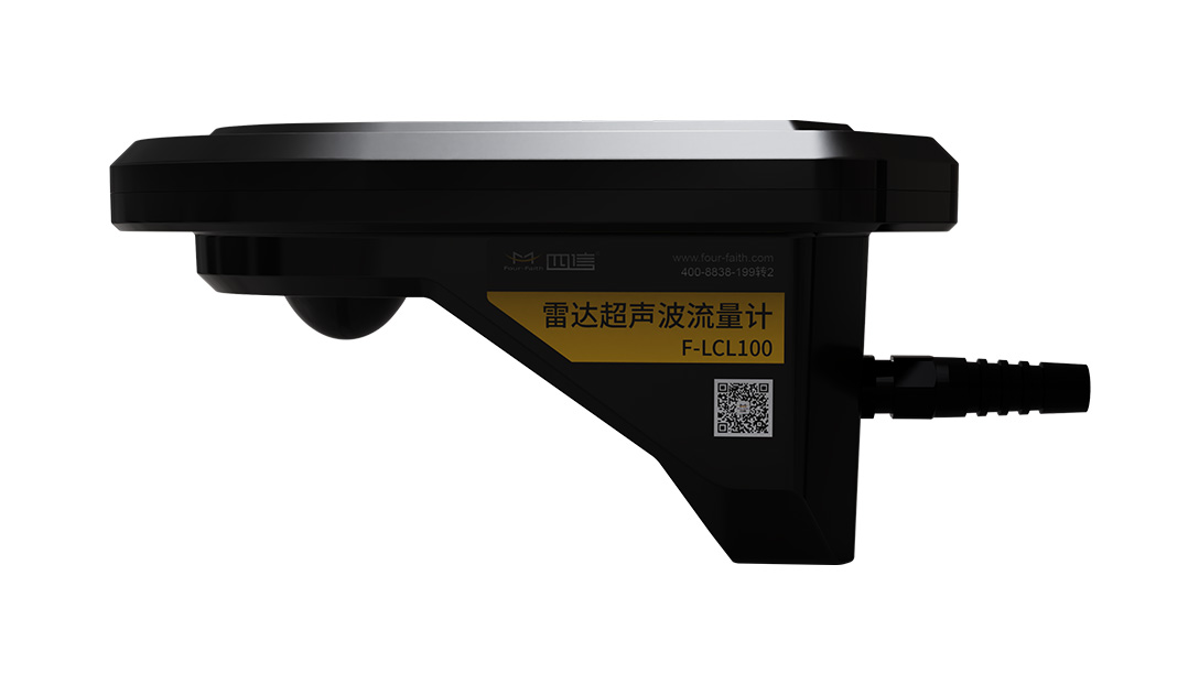
This tutorial is compiled based on the *F-LCL100 Radar-Ultrasonic Flowmeter User Manual V1.2* from Four-Faith. It introduces the dual-mode hybrid flow measurement principle, installation essentials and RS485 commissioning methods to help you complete flow monitoring deployment.
Product Overview: Dual-Mode Hybrid Flow Measurement
The F-LCL100 measures water velocity and flow in culverts, box culverts and pipelines by combining ultrasonic and radar waves. The measurement point is located above the pipe without disturbing the flow field, enabling seamless measurement across high and low water levels. With no moving parts, the device avoids sediment blockage and weed entanglement, making it suitable for harsh environments with high suspended solids and floating debris, including humid, flood-prone conditions.
Dual-Mode Flow Measurement Principle: Real-Time Monitoring Across All States
When the pipe is not full, the radar performs non-contact flow measurement: based on the cross-section parameters and the built-in hydraulic model, it converts the surface velocity into the cross-sectional average velocity and calculates the flow rate using the velocity-area method. Once the device is submerged, it switches to ultrasonic contact flow measurement, which combined with pressure-based water level measurement handles partially submerged and full-pipe metering. The two are summed to produce real-time flow across all states.
Before Installation: Environment and Height Selection
✅️ The channel should be straight with concentrated flow, a regular and hardened cross-section, and free of blocking stones and turbulent eddies;
✅️ Avoid weeds or slopes directly beneath the radar, and keep the transmission direction clear of strong reflective obstructions such as water and metal;
✅️ Choose a moderate installation height: too high weakens the echo and makes low velocities difficult to measure, while too low increases theft risk.
Installation and Wiring Essentials
✅️ TThe protruding circular radar antenna must face downward; the radar must not be obstructed and should be installed at the center of the channel;/p>
✅️ AThe flowmeter beam should face the upstream direction and remain horizontally parallel to the flow direction;
✅️ CThe power cable (+ red / − black) and the 485 cable (A blue / B green) must run in two separate shielded cables; the power supply is 8–15 VDC.
RS485 Commissioning: Reading Velocity and Water Level
The device uses the MODBUS RTU protocol with a default baud rate of 9600 and a slave address of 01. The master sends "address + function code 03H + start register + quantity + CRC" to read data. For example, `01 03 00 00 00 02 C4 0B` reads velocity (register 0x0000); water level at 0x0002 and real-time flow at 0x0008 follow the same format. A slave response of `01 03 04 42 48 00 00 6E 5D` indicates a displayed reading of 50.0.
Once installation and commissioning are complete, you can remotely read velocity, water level and real-time flow to achieve full-state flow monitoring. For detailed parameters, refer to the original user manual.