 Four-Faith IoT

F9164-LT500 Low-Power Telemetry Terminal Installation Guide
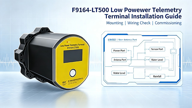
This document serves as the official installation guide for the F9164‑LT500 Low-Power Telemetry Terminal. It describes unpacking inspection, wiring, device configuration, groundwater monitoring well deployment, firmware upgrade and basic troubleshooting to help field engineers complete on-site commissioning safely and correctly.
1. Unpacking Inspection
Check all accessories upon unpacking: terminal main unit, antennas, sensor cable clamps, Type‑C data cable, waterproof wiring kit, power adapter, certificate of conformity and warranty card. Verify that the main enclosure has no dents or damage and all accessories are complete before installation. Retain packaging materials properly for equipment transportation.
2. Wiring Operations
Connect probe cables to corresponding interfaces according to sensor signal types: RS485 sensors to RS485 serial port; 4‑20mA signals to analog AI channels; rain gauges and digital input devices to corresponding optional interfaces.
Install the cellular SMB antenna and LoRa MCX‑KE antenna respectively. Keep antennas away from metal housings to prevent signal shielding.
Seal all cable connectors with the supplied waterproof kit to maintain the IP68 protection rating and avoid equipment damage caused by water seepage in wells. For solar power supply, connect the solar panel to the 7‑24V solar charging port.
3. Device Wake-up and Parameter Configuration
After wiring, wake up the terminal via the button. Check the 2.4-inch LCD screen to confirm battery level, network signal and readings of each measurement channel are normal.
Three configuration methods are supported: on-site commissioning via Android Bluetooth APP, local configuration through RS232 serial tool, and remote configuration via cloud platform.
Set the operation mode based on site conditions. For field battery-powered applications, self-report mode is recommended to realize sleep-wake reporting and maximize battery life. Use compatible mode when on-demand data polling is required. Configure key parameters including acquisition interval, alarm thresholds and reporting server address.
4. On-site Deployment (Groundwater Monitoring Well Scenario)
Place the main unit inside the protective barrel of the groundwater monitoring well. Lower the sensor probe along the well pipe to the specified burial depth, and secure the cable with cable clips to prevent the probe from pulling the wiring due to gravity. Position the main unit away from standing water, and reserve sufficient space for antennas for stable signal transmission and reception. Recheck screen readings after installation to ensure normal sensor data collection.
5. Firmware Upgrade (As Required)
Three upgrade options are available: local upgrade via serial port, on-site upgrade via Bluetooth APP, and remote upgrade through cloud platform. Do not cut off power during firmware upgrade to avoid firmware corruption.
6. Post-installation Inspection & Simple Troubleshooting
After full installation, monitor for 1–2 reporting cycles to confirm data is uploaded to the platform normally.
- Device fails to wake up: Check battery level and wiring terminals.
- No data uploaded: Verify SIM card, antennas, operation mode and server parameters.
- Abnormal readings: Recheck wiring and channel type configuration.
- Excessive battery drain: Reduce data acquisition & reporting frequency and enable self-report sleep mode.
Note: The equipment shall be installed under the guidance of professional engineers. Cable joints must not be submerged in water.